A breadboard is essentially the frame upon which one builds a circuit. It consists of two columns of 30 holes on either side of the breadboard which represent power and ground, and 30 rows of 10 holes, which are separated into groups of 5 by a channel in the middle.
The two columns of holes on the far sides of the breadboard are known as rails. One column of 30 holes is marked with a “+” and has a red line drawn down the side, and the other is marked with a “-” and has a blue line drawn down the side. The red column marked with the “+” is the power, and the blue column marked with the “-” is ground.
All of the power holes are directly connected to each other, and all of the ground holes are directly connected to each other. Tools such as potentiometers, photo cells, etc., are not directly plugged into the power or ground rail- rather, they are plugged in the middle of the breadboard and connected to the power/ground rail by a red or black wire, respectively. To connect part of a circuit to power or ground, the part of the circuit must be on the same side of the channel as the power/ground rail.
The middle of the breadboard is where the aforementioned tools (and others) are plugged in. As previously mentioned, it consists of 30 rows of 10 holes, which are further separated into groups of 5 by a channel that runs down the middle. All of the holes in a single horizontal row of 5 are directly connected to each other.
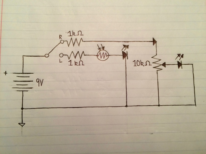 My schematic for circuit #3 + potentiometer-controlled LED + photo cell.
Multimeters are devices used to measure current, voltage, and resistance in a circuit. There are both digital and analog multimeters– in lab, we used digital multimeters. There are several settings on the dial of a multimeter: V with a tilde next to it, which stands for AC voltage; V with three short dashes on top of one large one, which stands for DC voltage, and the Ω symbol, which represents resistance. They have two probes- one red and one black.
Multimeters can help troubleshoot circuits in a variety of ways. First, you can use them to test to see if your battery is functioning properly. In order to do this, you set the dial to the correct DC voltage dial (for example, when using a 9 V battery, you would set the dial to 20 V), and connect the black probe to the negative end of the battery and the red probe to the positive end of the battery. The voltage of the battery will be displayed on the screen of the multimeter.
Multimeters can also be used to help ensure that you have the correct amount of current, voltage, and/or resistance within your circuit.
http://mk4937analogelectronicslab.weebly.com/blog/final-project-report
I really liked David’s project- I thought it was well designed, and I liked the variety of effects (tremolo, vibrato, etc.) that his circuit could create. I also appreciated how clearly laid out everything was on his breadboard, as it made the circuit more streamlined and easier for me to understand.
https://jselectronicsblog.wordpress.com/2016/05/04/final-project-synth-clarinet/
This project pretty much blew me away (no pun intended). I wasn’t aware that it was possible to use a breadboard to create an instrument that can sense breath input. The quality of the sound is pretty great, too.
https://jayesosa.wordpress.com/2016/04/27/final-report-unfinished/
Jaye’s project was really interesting, and I liked how clearly everything was laid out. I particularly liked how she implemented a fairly complex working relationship between the potentiometer, LED light, and the light sensitive resistor.
